Power source library
I've made it my quest to create OOP classes for Arduino. Read about that in this blogpost if you need some more context.
This class is to control a PC power supply in order to provide power-demanding devices in your setup.
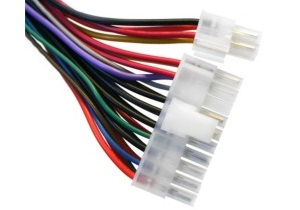
Since 1993 all power supplies have an ATX plug. This plug can have 20 or 24 pins or it can be a hybrid, containing a 20 pins plug and a 4 pins plug that can be linked together, like the one on this photo:

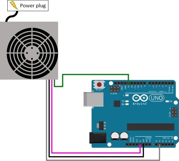
From this plug we need the green wire, the purple wire, the gray wire and a black wire. For the black wires it does not matter which one you choose, all black wires are ground. If your ATX connector doesn't have a gray wire, you can also connect one of the red wires to your Arduino instead of the gray wire. In that case it doesn't matter which red cable you take:

Whenever the power plug is connected the purple wire is always 5V with a low amperage. This is more than enough to power the Arduino, but not to power a lot of extra devices.
See the example source here to control the power supply.
When you call the turnOn() method the power source is turned on, and these wires are powered with a higher amperage:
| Wire color | Voltage |
|---|---|
| Orange | +3.3V DC |
| Red | +5V DC |
| Yellow | +12V DC |
| Blue | -12V DC |
The gray wire (or red wire if you don't have a gray wire) is +5V when the power supply works as expected. In case the power supply stops working as expected, for example due to an overload protection, the library will automatically reset the power supply.
The power source library can be found here on GitHub.
It uses the BaseTimedElement base class which can be found here on GitHub.


